
A unique jig to test a cantilever wood structureSolid Mechanics, Fall 2014
Machine Shop Instructor |
Skills
Solidworks FEA Connection modeling Machining Tutorial design |
|
|
Traditionally, students in Solid Mechanics have designed a wooden bridge to test under 3 point bending. While working as a Technical Instructor in the Machine Shop I was tasked with designing a system for building and testing a cantilever structure that could include cable supports. The jig would need to mount to the Instron testing machine on a bolt pattern centered under the loading point. It also needed to allow for quick and easy mounting of each structure. After settling on some rough dimensions and basic design, I explored several options in SolidWorks and used FEA analysis to determine potential failure modes in the wooden structure and aluminum fixtures. The goal was to minimize stress in connections to the jig, and minimize the jig’s displacement.
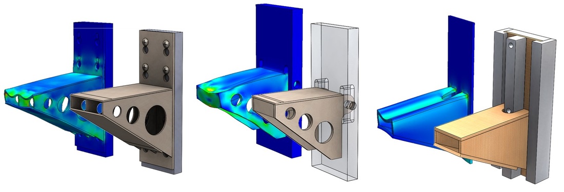
Testing three different options for mounting a wood structure using SolidWorks FEA analysis
Our laser cutter can only cut through ¼” plywood, so that limited the back plate thickness. To reinforce the back plate, I decided that students could glue the laser cut ¼” sheet to a piece of ½” plywood we could pre cut on a table saw. With that, I could make a simpler jig that gave full flexibility for cables and sufficient space for creative design while having a solidly attached back plate that was easy to mount with no fasteners.

The assembly scheme for students to use in making their structures to allow for a 3/4" thick rigid backplate
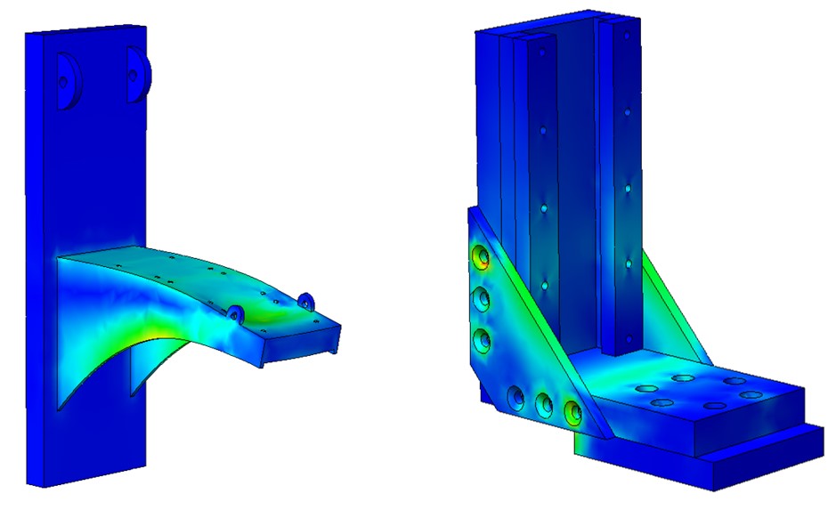
FEA analysis of the final jig and the wood test structure

Completed jig with the wood test structure sliding into place, SolidWorks model of the final design
After finalizing the design of the jig, I machined and assembled the pieces. I tested the wooden test structure in the jig on the Instron and compared the results to the FEA analysis in SoldiWorks. I used the data from the testing to evaluate different options for modeling the cables in SolidWorks. Using what I learned, I prepared a detailed tutorial which I used in class to teach students how to best use SolidWorks to simulate their structures and predict failure loads. On testing day, the jig worked flawlessly, allowing for rapid mounting and removal of structures.
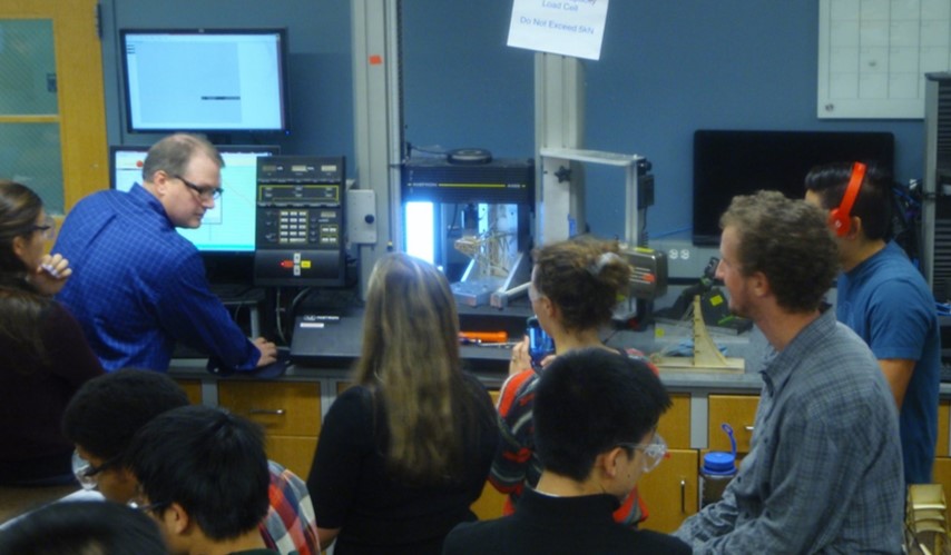
Test Day: Students watch as their structures are loaded on the Instron
