
Unconventional Human Powered VehicleAdvanced Computer Aided Mechanical Engineering Design, Spring 2013
Lead SolidWorks Modeler |
Skills
SolidWorks Welment Modeling Machining, MIG Welding Ergonomics, human factors SolidWorks Composer |
|
|
Diwheels
For the final project in ENGS 146, we were challenged to design and build a pedal powered diwheel, a wheeled vehicle where the rider sits within two large hoop wheels. This was the first year this project was done; even our professor didn’t know how well it would work out. In a team of 4 with nothing more than salvaged bike parts from two old bikes, two steel wheels, and limited materials for the frame and other parts we needed to have a functional diwheel ready to compete in a class race in 4 weeks.
We only needed 3 weeks to get rolling. And we won the final race by a longshot. How did we pull it off?
With such limited time, there was no way to develop and build multiple prototypes. We had to do all of our design iteration in SolidWorks. Beyond that, we had to plan on being fast and flexible, adapting to design challenges and overcoming them on the fly. "Do it live" became our design mantra.
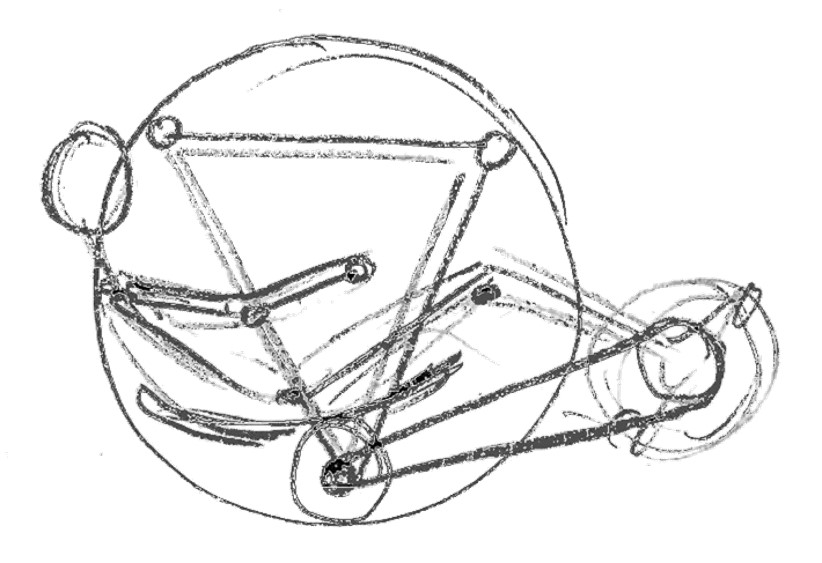
How to fit a rider into the frame
|
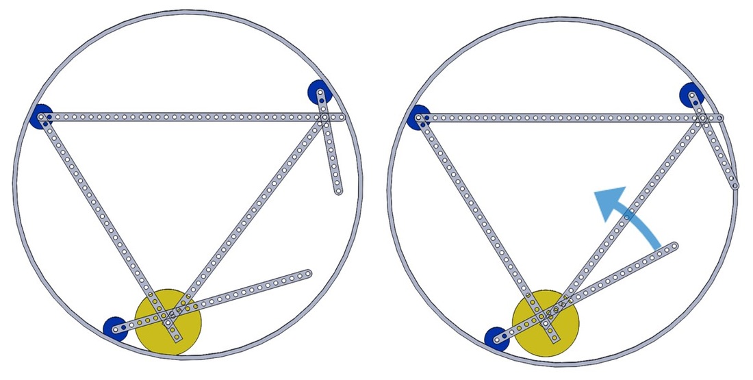
our simple turning system. pulling the lever disengages the drivewheel (right)
|
The central challenge of controlling a diwheel is steering, which requires differential driving of the wheels. We considered traditional mechanisms of a differential or a pair of disk or belt clutches, but wanted something that was much simpler. In our brainstorming, we came up with the idea of using the drive wheels as a sort of clutch, with a lever on each side to lift them off of the hoop wheels, which would allow the diwheel to pivot around the disengaged side to turn. Once I tested the feasibility of the mechanism in SolidWorks I used a flexible base sketch to create the frame, allowing easy changes to geometry and rapid design iterations.
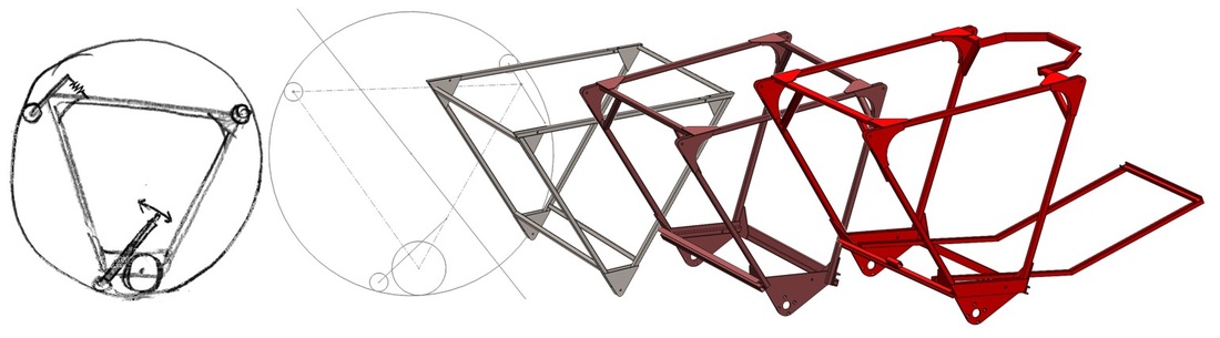
I took our design from a rough sketch to a final frame model in SolidWorks
With over a foot of height difference among our team members, we knew getting the right pedal and seat geometry would be a challenge. We designed the frame so we could adjust both the angle and length of the pedal support. Once we found a position that worked for all of us, we welded the support in place with another structural member, forming a sturdy triangle.
With limited time, we needed to limit the complexity of fabrication and assembly required to get our diwheel rolling. Our design has only 3 different machined parts: the aluminum wheels, bearing blocks, and a cassette hub to attach the bike cassette to our fixed axle. Everything else was CNC plasma cut or cut on a bandsaw. I designed the frame so it could be easily welded without requiring any jigs or measuring, using only the plasma cut gussets for alignment. We managed to get our diwheel to a rideable state in only 5 days of fabrication.
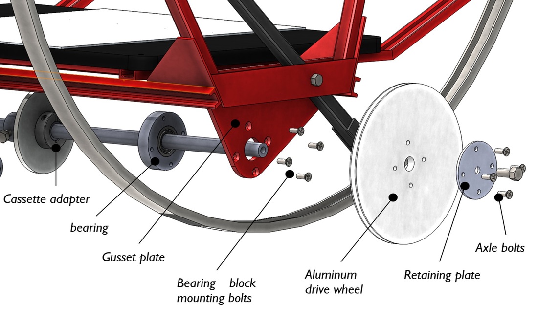
Exploded view out one side of our fixed-axle drive line
|
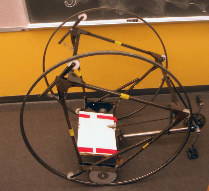
The diwheel in its first rideable state
|
Having our diwheel rolling a full week before the race gave us plenty of time to fine tune the drive system. We tried different gears and adjusted chain tension to get optimum power transfer. Our simple, rugged design came through; we won the final race and were the only team to not have any mechanical failures during competition.
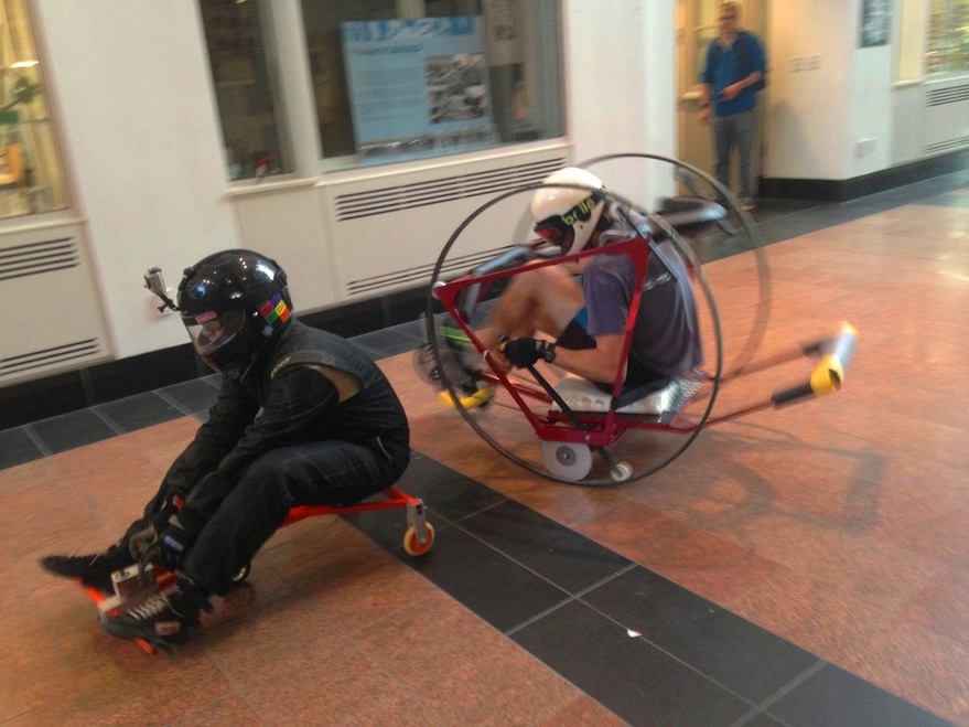
A year later my teammate Scott and I worked as teaching assistants for the class, helping another class of students build their own diwheels in addition to developing, testing, and managing the other smaller class projects. Scott joined the class on race day in our diwheel, making second place out of 7 teams.
In the third year of diwheels, all teams designed drive systems that relied on a differential for steering. Even against this new generation of highly efficient drive systems, I held my own in the Scorpion which was again the second fastest diwheel on the course.
|
My video of the 2013 class race
|
My video of the 2014 class race
|
A tour of our design I created using SolidWorks Composer
Playing around with our diwheel and a wiggle car, a previous ENGS 146 design project
