
An Intra-Osseous Needle Placement GuideThayer School of Engineering, Winter 2015
Lead Designer, Cofounder This product has not been cleared for use by the US FDA Read more at: iometry.com |
|

|
Skills
Iterative Prototyping Medical Device Design Human Factors, Ergonomics User Manual Design User Testing |
|
|
How can we make Intra-Osseous infusion simple enough for anyone?
While working as the Thayer School Design Fellow, I worked on a team of students, graduates, and professors to design a simple guide that would allow a non-medically trained user to safely and reliably place an intra-osseous needle in the tibia. An intra-osseous (IO) infusion puts fluids directly into the marrow of a bone, which is a faster and more reliable way to administer life saving fluid to severely dehydrated patients. To set an IO line, a special self drilling needle is inserted into the tibia with a small handheld drill driver.
|
|
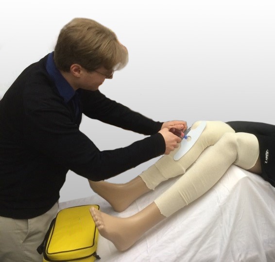
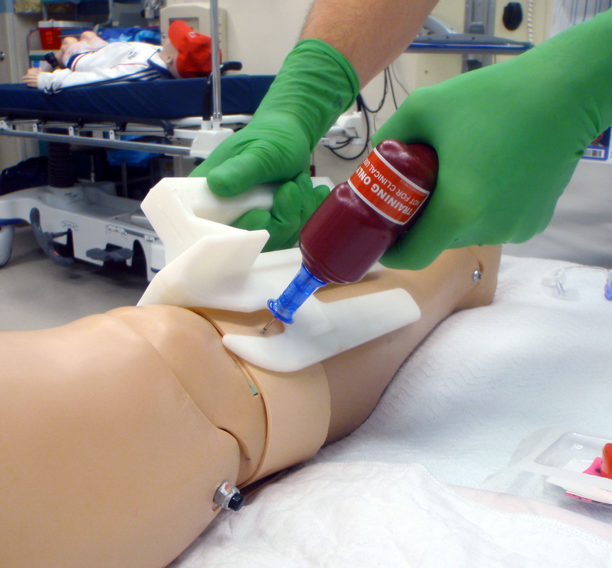
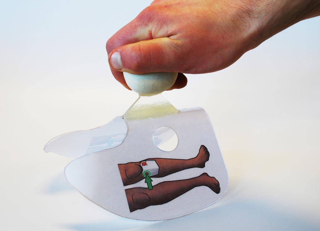
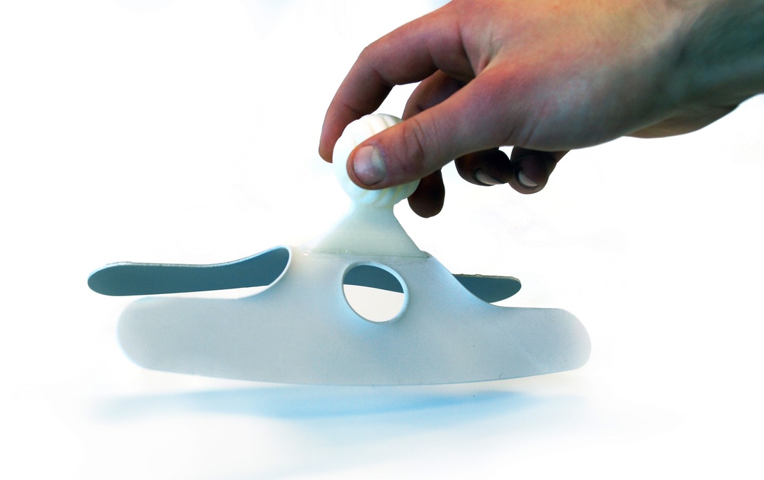
Demonstrating the placement of an IO line using our prototypes on our user testing mannequin
Stage 1: Initial Development
The project started as a one-week intensive design challenge, with a goal of creating a design in order to get funding for further development. The team members were myself, Thayer School Professor Doug Van Citters, and Alex Slocum Jr, a mechanical engineer from MIT and medical student at Marshal University School of Medicine. In our initial design brainstorm session, Doug and Alex outlined what the main specs of the guide would be:
- reliably locate the correct insertion site
- easily manufacturable, preferably injection molded
- simple to use
Working with feedback from Professor Van Citters, I made over 15 iterations of our initial concept for the guide. At the end of the week, I had produced a SolidWorks model of a guide design that could be easily injection molded. I 3D Printed our final design and we tested the basic use at the medical simulation lab at Dartmouth Hitchcock Medical Center, taking pictures and video to demonstrate the use of the prototype.
|
|
|
In 7 days we went from an initial design session, through several iterations and major design changes, to testing our final prototype in the medical simulation lab
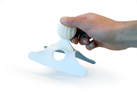
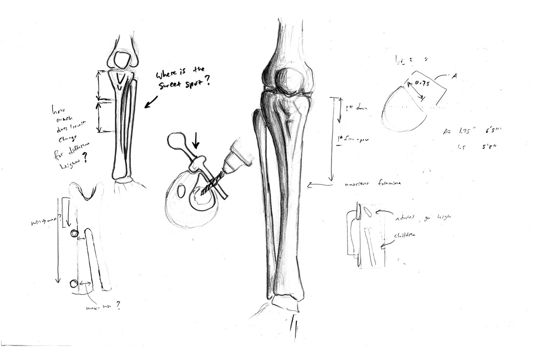
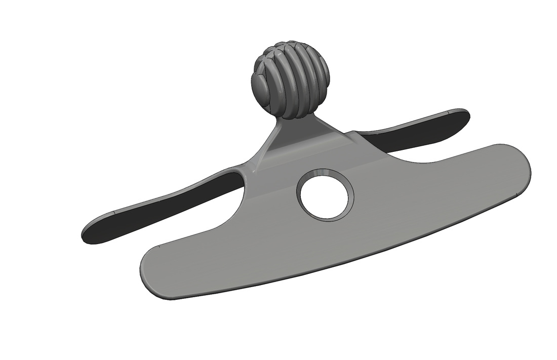
At this stage, we still did not know what the exact location for proper placement would be, and how that would change with different age individuals, so the guide was designed with a slot to allow for different locations. This was to be finalized in phase 2 of the project, once anthropometric data could be acquired. The slot gave the guide the look of an ice skate, and that became the name of our first design.
At this stage, we still did not know what the exact location for proper placement would be, and how that would change with different age individuals, so the guide was designed with a slot to allow for different locations. This was to be finalized in phase 2 of the project, once anthropometric data could be acquired. The slot gave the guide the look of an ice skate, and that became the name of our first design.
|
|
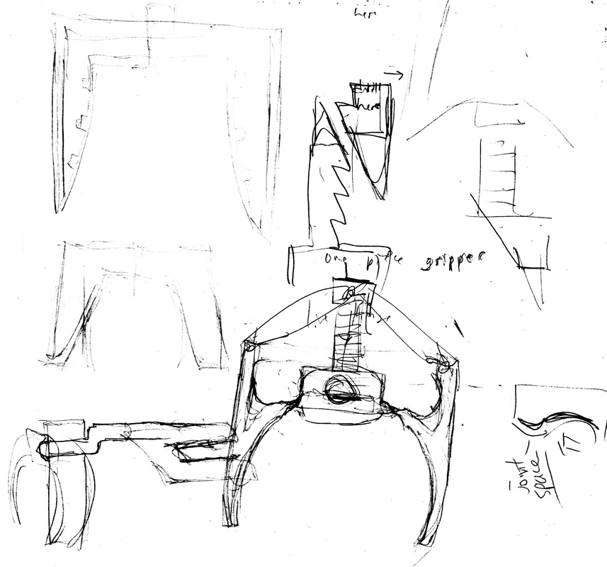
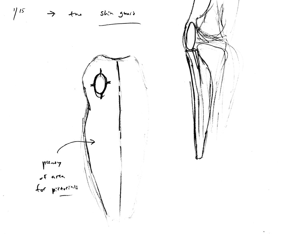
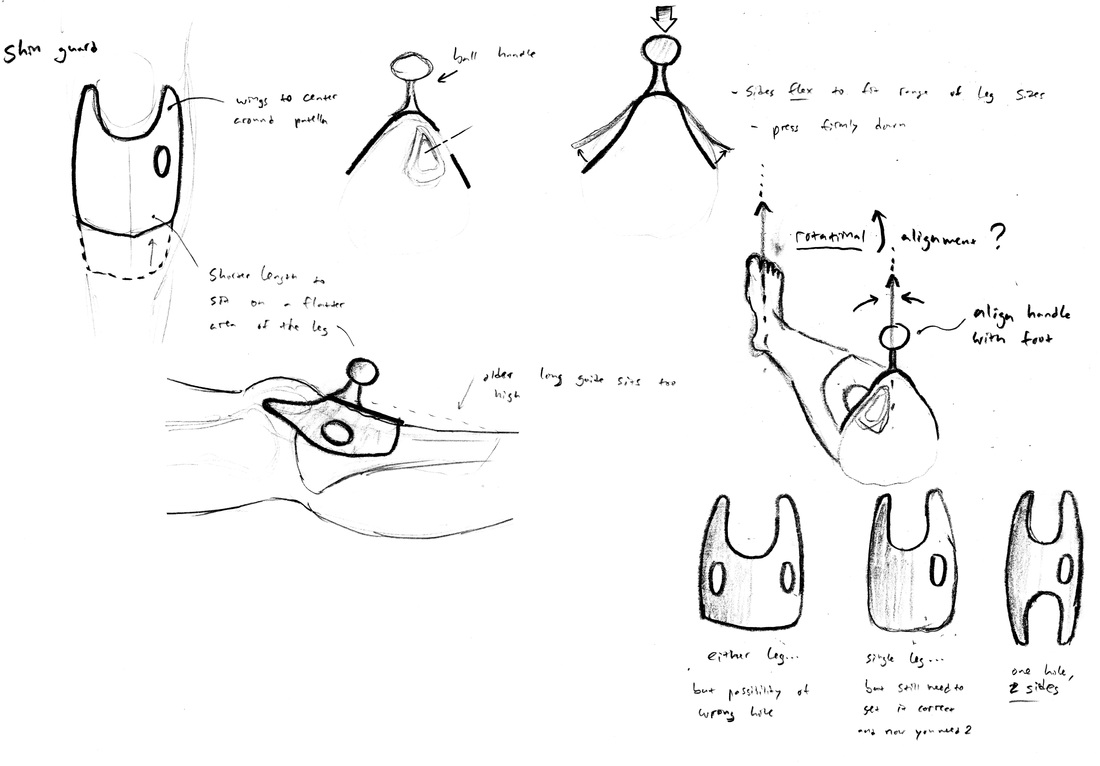
Sketching the bone geometry in the area of interest to understand where exactly we need to hit
Stage 2: Research and Development
In preparation for phase 2, we expanded the team. Steven Reinitz, a research associate at Thayer, became our project manager and head of user testing. Several undergraduate engineers joined the team as well to provide more variety to our brainstorming and ideation and to help with prototyping and testing. After narrowing down our design to the final Ice Skate in phase 1, we began phase 2 by re-opening the design space to explore additional concepts.
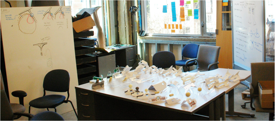
The design loft: a corner of an unused lab in Thayer School
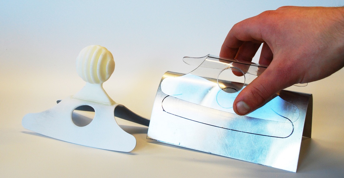
As lead designer, I took charge of fabricating prototypes. After group brainstorm sessions, I would make quick mock ups of our designs in foam core, thermoformed plastic, polyurethane foam, and laser cut actrylic. With such simple fabrication, it was possible to make prototypes by the dozen, allowing us to rapidly explore many different variations on our designs. Our initial goal was to explore a wide range of possible designs, which we would later narrow down and finalize through user testing and group critiques.

Prototype development
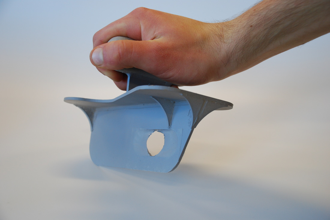
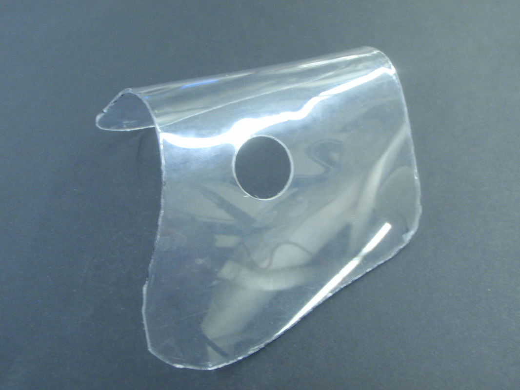
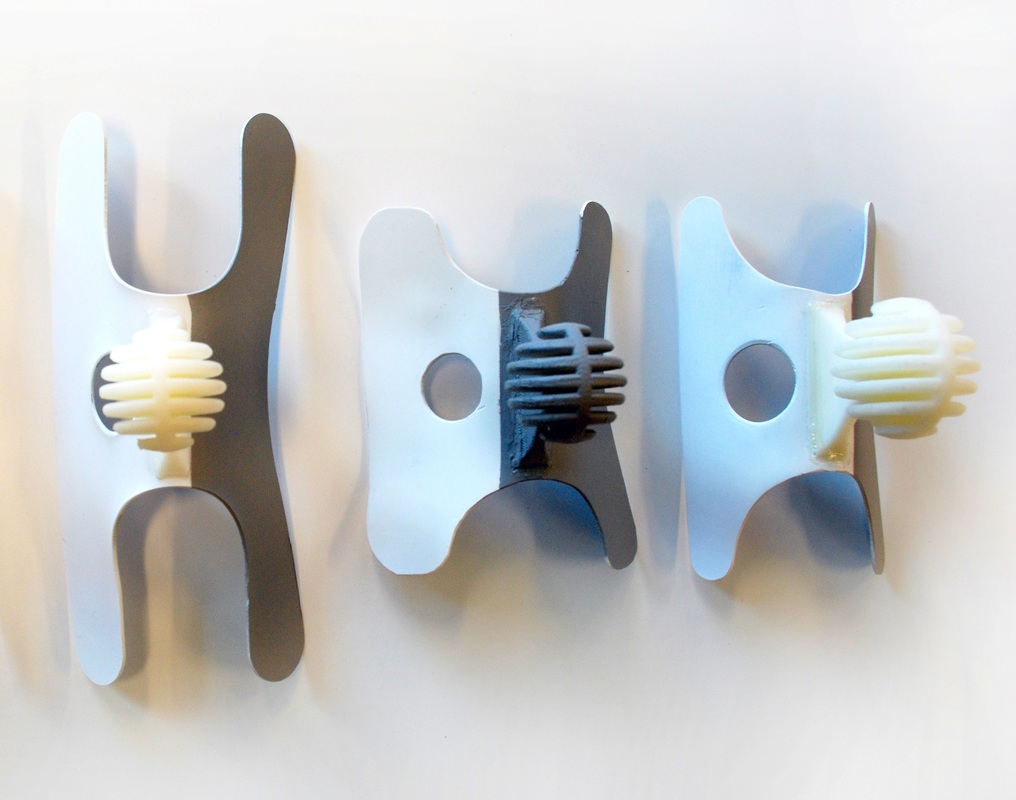
We continued working with the Ice Skate design from Phase I, and I made some design changes to address the concerns we had with the initial design. I tried rotating the handle 90 degrees to give more leverage and control, as well as shortening the overall guide. I also made curved ribs to let the guide sit more naturally on the leg. This design became the Modified Ice Skate. The other main addition to our prototypes was the Shin Guard, a curved piece of plastic that fit below the knee with a hole in the correct insertion site. After much modification, this concept would eventually evolve into our final prototype.
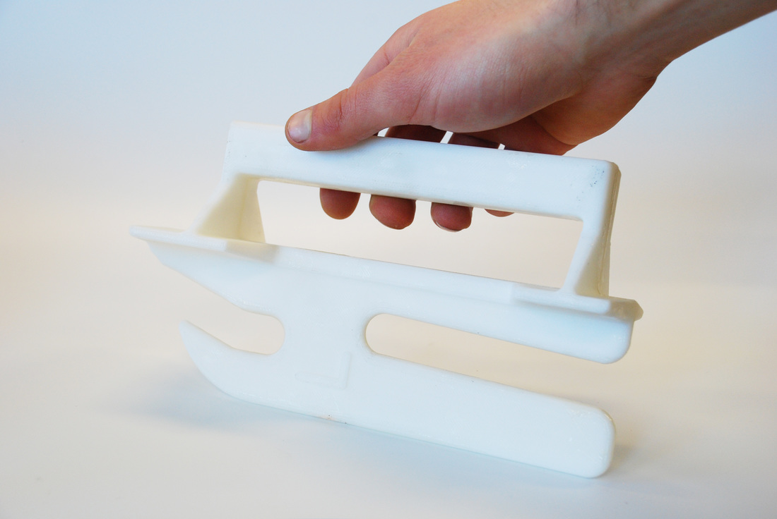
The "Ice Skate": Phase 1
|
Modified Ice Skate: Phase 2
|

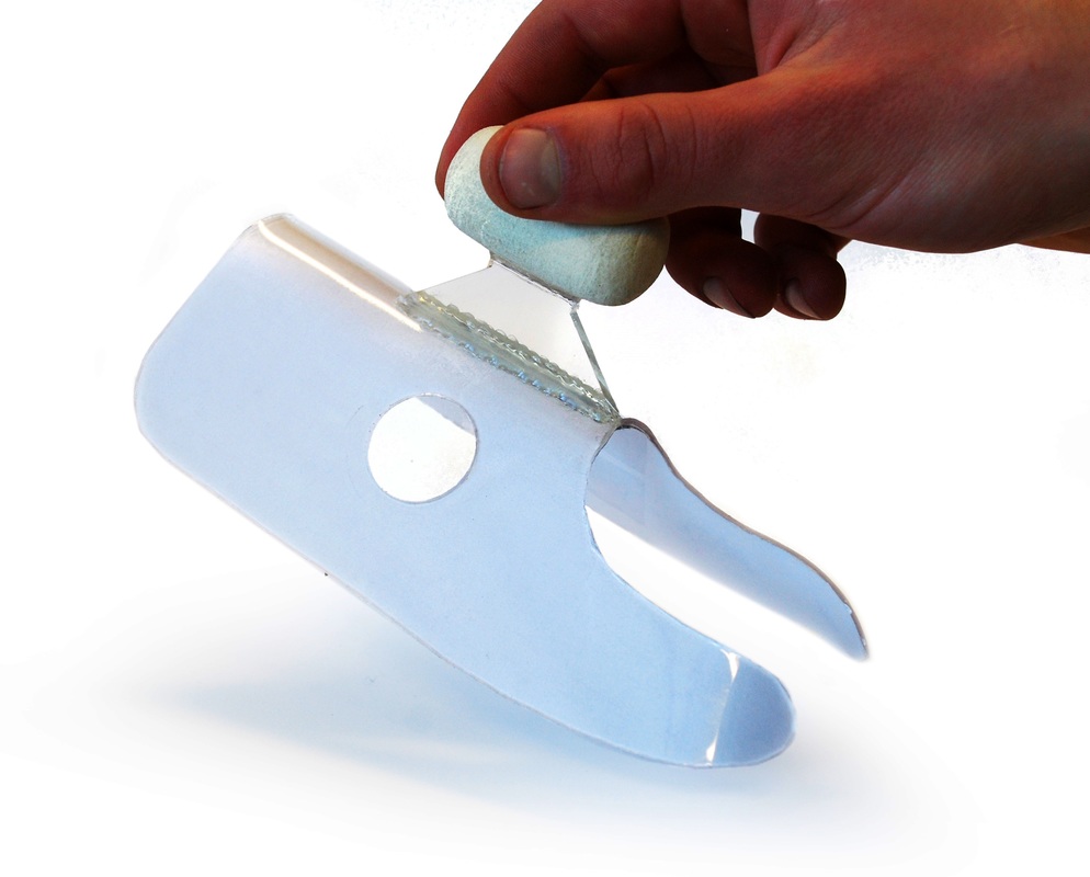
"Shin Guard" with handle
|
|
The Shin Guard is born: take one side of the Ice Skate, and with a few modifications it became a contoured shape to fit over the leg. In future iterations, I added a handle for easier control and ergonomics.

|
|
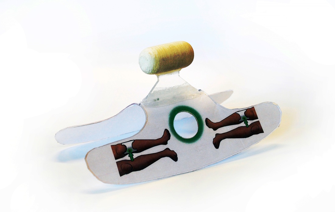
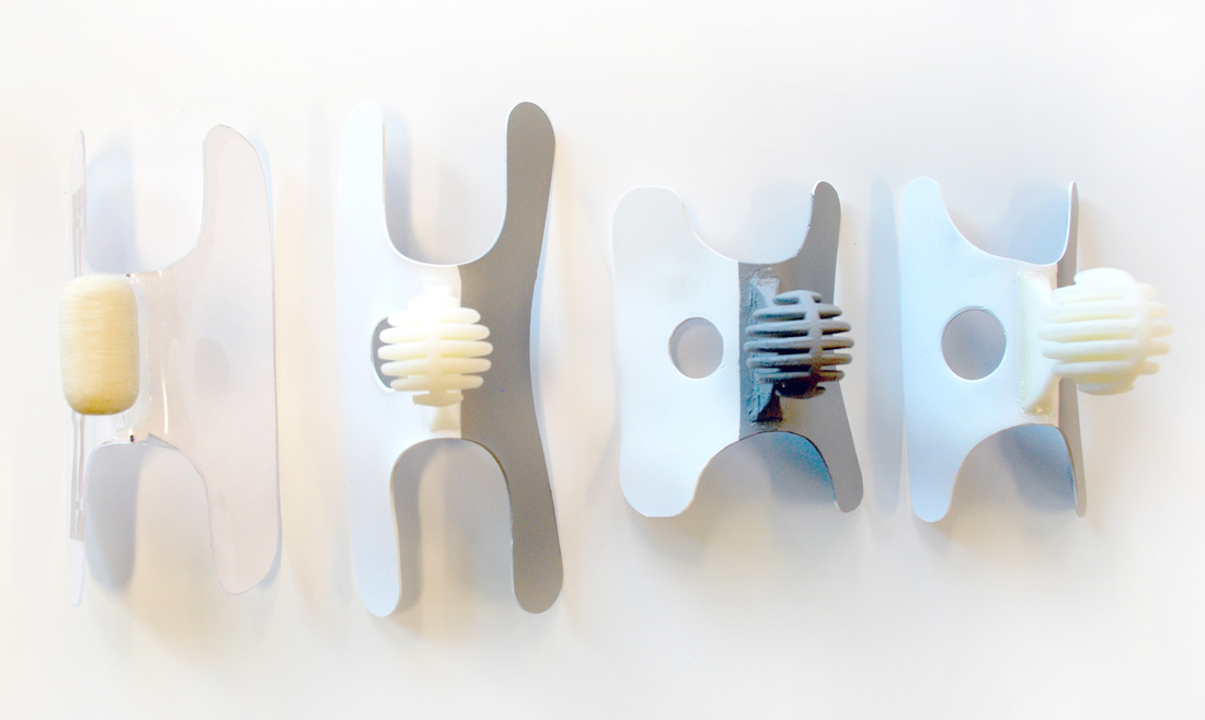
Key steps in the evolution of the Shin Guard from first prototype to final design
|
|
|
|
|
|
|
Manual Design
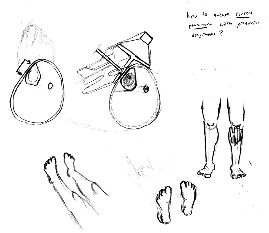
Designing an instructional manual was an essential part of this project, since the end goal was a guide that would permit untrained users to place an IO line. This manual would need to be pictorial, with no words and no symbols not universally understood
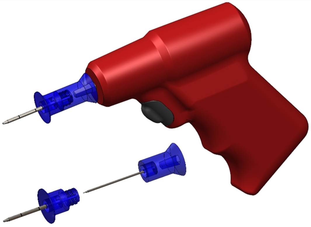
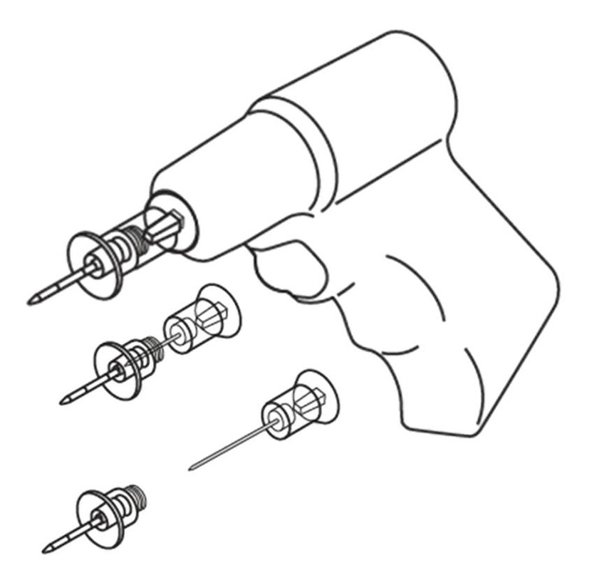
. We turned to Funnel Inc., a graphic design firm specializing in manuals and infographics, to design our manual. We provided their designers with photos of the proper use of the guide and detailed SolidWorks models I had made of the guide, IO gun, and needles. Funnel Inc. put together a manual, which we worked with them to refine through our user testing. From user feedback and testing results, we determined areas to improve the manual to eliminate confusion. The final manual was the result of several iterations and was validated by successful user tests. Our final manual was a combination of drawings, materials, and user testing from our design team and Funnel's overall concept and drawing set,. right: some of the initial manual components I experimented with. These were used by Funnel Inc as reference material for their design
|

|
I modeled our guide as well as the IO gun and needles in SolidWorks. Funnel Inc used these models to create accurate graphics for the manual
|
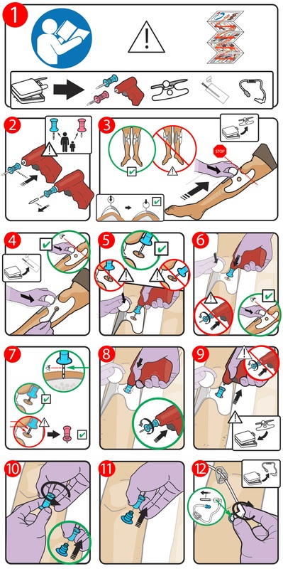
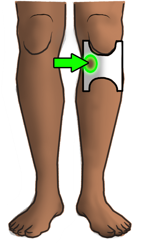
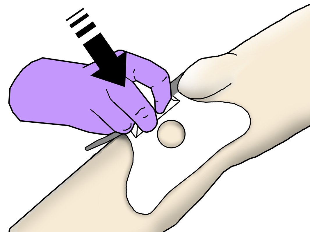
Final manual design
|

|
User Testing
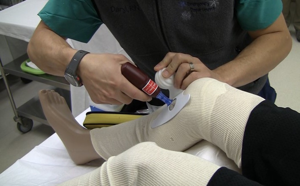
Our user testing helped to guide us through the final design changes on both our guide and the manual that would accompany it. I built our test setup using an IO training leg and a mannequin. The training leg has a removable tibia section with realistic skin patch to simulate drilling through tissue into bone. The accuracy of users insertion was measured on the target area. Participants were given an IO kit, our guide, and our manual with no other directions given..
|

Steven Reinitz demonstrates the user testing setup
|
Design Refinement
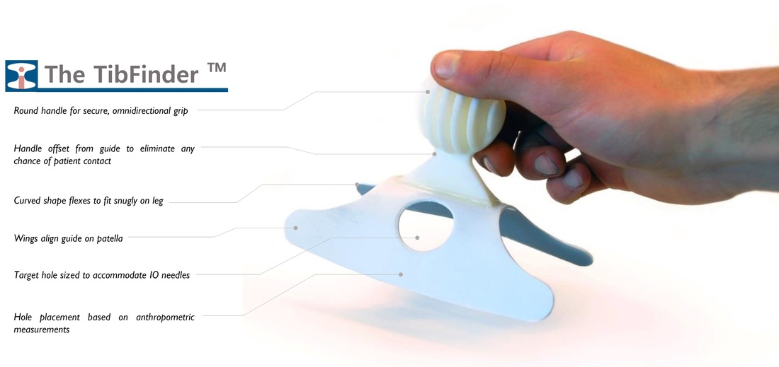
We were close to a finished design when we started designing the manual, but still had not conducted enough controlled user testing to determine how untrained users would handle the guide. The first design we tested with had long alignment wings, making a snug fit but requiring firm pressure to flex the guide and properly seat it in place. Users were apprehensive of applying much force to the device, so we widened and shortened the alignment wings, and opened up the overall curve of the guide. Users were able to properly use the guide, but it was possible to easily rotate the guide on the leg, resulting on improper alignment.
For the final iteration, we kept the short, wide alignment wings, but tightened the curvature of the guide to require some force to seat it against the leg and provide correct alignment. This combination was successful in testing; paired with our revised manual, users showed excellent success in accurately locating the target site and properly inserting the IO needle
For the final iteration, we kept the short, wide alignment wings, but tightened the curvature of the guide to require some force to seat it against the leg and provide correct alignment. This combination was successful in testing; paired with our revised manual, users showed excellent success in accurately locating the target site and properly inserting the IO needle
Final evolution to the finished prototype
|
Some of the final design modifications of the Shin Guard
|
|
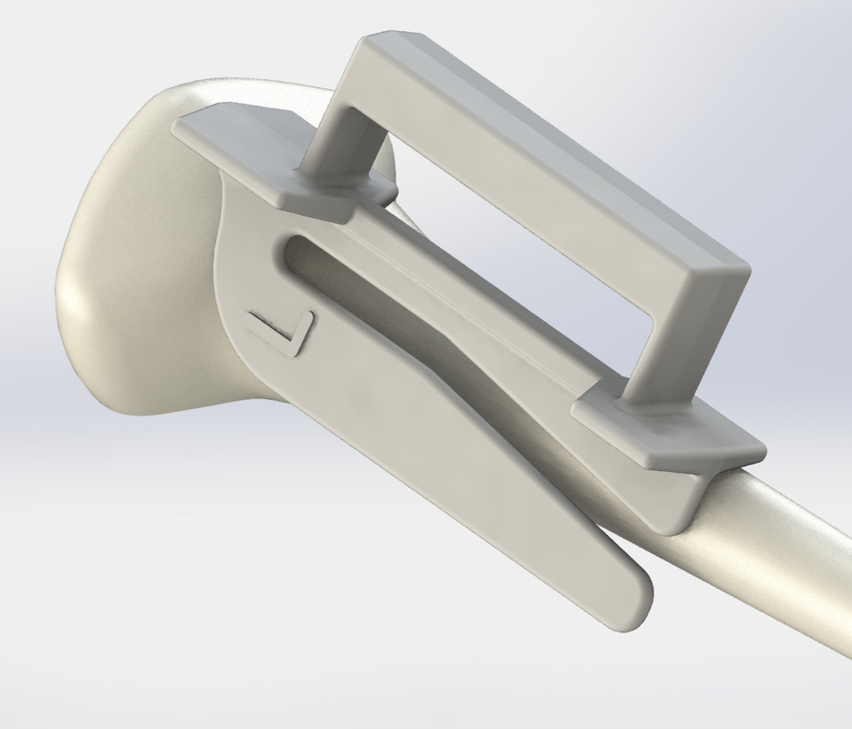
I fabricated several identical final prototypes for user testing. The main body of the guide is a sheet of ABS milled to shape on a CNC mill, then thermoformed over an aluminum mold. The 3D printed handle is bonded to the molded sheet with a flexible thermoplastic adhesive, allowing the guide to flex without breaking the glue joint. In addition to my handmade prototypes, I worked on modeling the guide in SolidWorks and began optimizing the design for injection molding. I created one version of the guide as a single piece, which would require a 3 part mold. I also made a version with a separate handle that could be made with only a 2 part mold. We worked with ProtoMolds to get feedback on our designs and get cost estimates for manufacturing. |
making the final protytpes
|
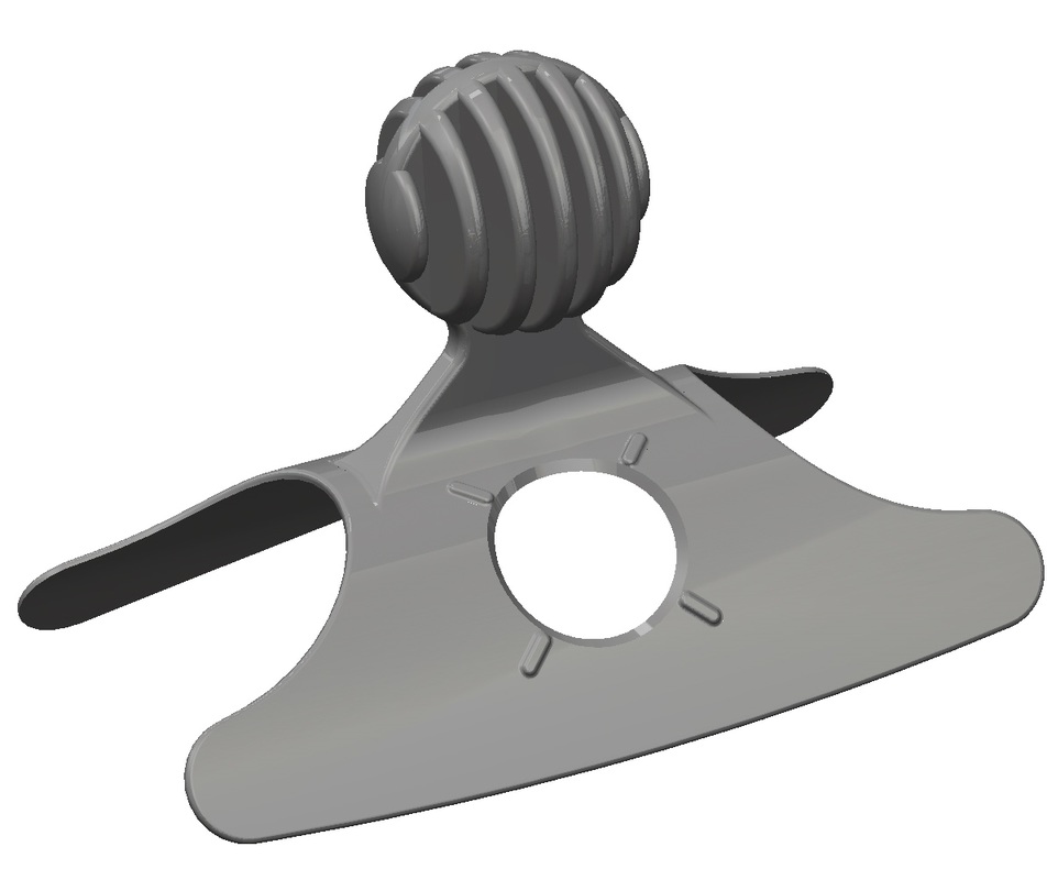
rendering of single piece guide
|
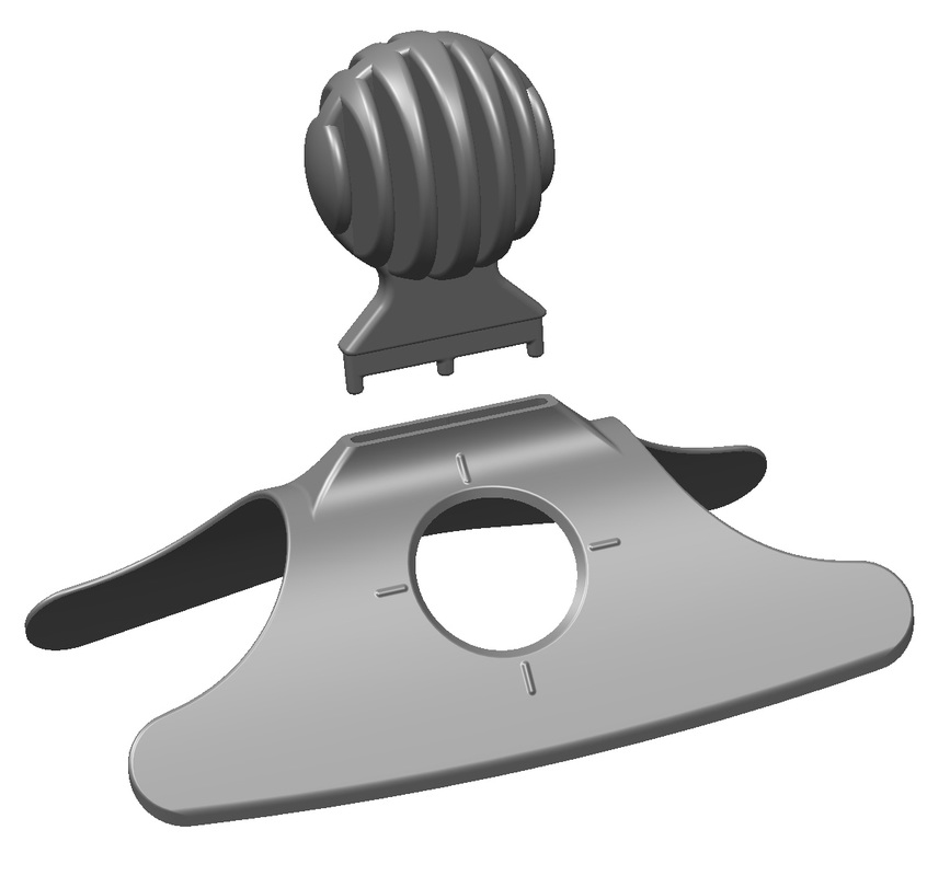
rendering of two-part guide
|
Moving Forward
My work on the project concluded in March 2015. However, the Tib-Finder project continues today with external funding and is moving through the regulatory and manufacturing pathways. Our final report and manual can be found on the IOMETRY, Inc. website.

